
Why do design codes introduce cracking coefficients?
Before diving in, ask yourself two key questions:
- What problem are the cracking coefficients in the codes actually simplifying?
- When we switch to the “standard” nonlinear analyses recommended by regulations such as ASCE 41, do these coefficients still matter?
If your answer is yes, you may wonder:
Then what extra benefit does nonlinear analysis bring? Don’t moment–curvature $M\text{–}\phi$ curves already capture concrete cracking at moments below the plastic moment?
1 Definition of the Cracking Coefficient
Consider a single reinforced-concrete section subjected to a given load combination.
With a fiber analysis in SAP2000, ETABS, OpenSees, … you can quickly obtain its $M\text{–}\phi$ diagram (Figure 1).
Cracking coefficient ($k_{\text{cr}}$) is defined as the ratio of the effective stiffness at that load to the gross (un-cracked, reinforcement-ignored) stiffness of the section:
$$
k_{\text{cr}} \;=\;
\frac{\displaystyle \frac{M}{\phi} \bigl|_{\text{current load}}}
{E_c I_g}
\tag{1}
$$
- $M$ Current bending moment
- $\phi$ Curvature at $M$ (slope of the line from the origin to the point $M,\phi$ on the curve)
- $E_c I_g$ Gross stiffness of the un-cracked concrete section
At service-level combinations (i.e., those designed not to drive the section beyond yield), Eq. (1) fully describes how much cracking degrades stiffness.
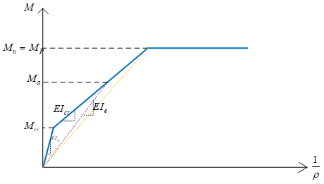
Figure 1 – Typical moment–curvature diagram for an RC beam with reinforcement below the balanced ratio.
2 How Codes Use $k_{\text{cr}}$ in Linear and Non-Linear Models
- Linear analysis in most codes replaces the gross stiffness with
$$
E_c I_{\text{eff}} \;=\; k_{\text{cr}}\,E_c I_g \tag{2}
$$
to mimic cracking in the pre-yield range. - Conventional nonlinear analyses (the bilinear plastic-hinge models in ASCE 41 or Publication 360) do not track the curved part of the $M\text{–}\phi$ relation explicitly; they adopt a single effective stiffness up to yield.
- You may omit $k_{\text{cr}}$ only if your element model already includes the full bilinear (or multi-linear) pre-yield behavior.
- Because $k_{\text{cr}}$ varies with moment,
- $k_{\text{cr}}=1$ for $M < M_{\text{cr}}$ (un-cracked)
- $k_{\text{cr}}<1$ for $M_{\text{cr}} \le M < M_p$ where $M_{\text{cr}}$ is the cracking moment and $M_p$ is the plastic moment.
3 Code-Specified Values (Ultimate-Strength Combinations)
Design codes often assume that ultimate combinations ideally push each section up to its plastic resistance.
Under that assumption, ACI 318-19 gives the fixed factors in the following Table.
Table 6.6.3.1.1 (a) — Moments of Inertia and Cross-Sectional Areas Permitted for Elastic Analysis at Factored-Load Level (ACI 318-19)
| Member / Condition | Moment of Inertia | Cross-Sectional Area for Axial Deformations | Cross-Sectional Area for Shear Deformations |
|---|---|---|---|
| Columns | $0.70 I_g$ | — | — |
| Walls – Uncracked | $0.70 I_g$ | $1.0 A_g$ | $b_w h$ |
| Walls – Cracked | $0.35 I_g$ | — | — |
| Beams | $0.35 I_g$ | — | — |
| Flat plates & flat slabs | $0.25 I_g$ | — | — |
ACI 318 also introduces an alternative (strain-based) method with variable factors (Table 6.6.3.1.1 (b) in the code). Current software seldom supports that approach in everyday practice.
4 Service-Load Combinations
For service combinations (concrete and steel limited to $0.6\,f_c’$), the allowable bending capacity can be found, and Eq. (1) reused.
ACI recommends a shortcut:
$$
k_{\text{cr, service}} \;\approx\; 1.4\,k_{\text{cr, ultimate}}
$$
5 Key Takeaways
- Cracking coefficients are a shortcut that fold the curved portion of the $M\text{–}\phi$ diagram into a single “effective” stiffness.
- They remain relevant in many “standard” nonlinear analyses because those hinge models start at yield.
- You may skip them only when your model explicitly includes the bilinear pre-yield branch.
- For beams, $k_{\text{cr}}\approx0.35$ at ultimate; for columns under axial load, $k_{\text{cr}}\approx0.70$ (ACI 318-19).
- Service-load factors can be taken as roughly 1.4 × ultimate.
References
- ACI 318-19 (2019). Building Code Requirements for Structural Concrete & Commentary, American Concrete Institute, Farmington Hills, MI.
- Moehle, J. P. (2014). Seismic Design of Reinforced Concrete Buildings, McGraw–Hill Education, New York, NY, 760 pp.

Your Comment